Products


MPD SFERA


The aim of the device.

The MPD SFERA is aimed for the following purposes:

To treat the products made of metals and alloys by plasma  in order to harden their surfaces and increase  their strength several fold.
To produce a low-temperature plasma with various densities of the charged particles 
To study fundamental processes in various plasmas and the properties of these plasmas.
To test and adjust the diagnostic plasma system.
To train the personal in operation with the plasma and experimental device  as well as with the diagnostic equipment for measuring plasma parameters.

Construction of the device.

MPD SFERA is a spherical chamber. Diameter of the chamber is 30 cm. In the chamber there are 5 ports with a passage diameter of 16 cm and  8 ports with a diameter of 3 cm. The ports are used for the installation of the plasma sources, for multipurpose vacuum introductions and for connection of the diagnostic equipment.

Microplasma treatment samples Photos.

Click photo to enlarge.

 Treated & not treated Treated Not treated Not treated & treated Treated


Click to enlarge Click to enlarge
Treated Treated In process In process


Plasma relativistic microwave amplifier

Similar to CPM:

  • operation principles & contrivance;

  • high microwave power: ~ 20 MW (now);

  • broad range of the mean frequency tuning : 4-fold (now).

Unlike CPM:

  • narrow outlet radiation spectrum width: ~ 1%;

Experiment:
“Terek-3-2”:  500 kV, 1.5 kA
 

Measurements:


Results:


Time-resolving semiconductor detector of high-power microwaves.

Purpose: to register temporal behavior of pulsed microwave field.

Advantage: extremely high reliability, no threat of destruction due to the absence of p-n transition. The semiconductor may be exposed to any level of pulsed rf-power without damage.

Operational principle: based on so-called "hot carriers". Under the influence of RF field the effective mass of carriers (electrons or holes) in the semiconductor rises, causing a rise of the total resistance of the semiconductor sample. The resistance variation is measured by applying electric current (bias), constant in the course of the pulse, and measuring the voltage. The level of RF power density > 1 kW/cm2. Temporal resolution lower than 1 ns. Output signal ~ 10 - 100 V from BNC or N-type socket.

Principal components: container 150*150*400 mm; Dewar vessel; semiconductor crystal in a waveguide, immersed in liquid nitrogen; bias source.

Modifications:

  1. rectangular waveguide (high frequencies, above X band);
  2. coaxial waveguide (low frequencies).


Ref.: O.T.Loza, L.E.Tsopp. "Detection of single high-power pulses of microwave radiation". Proc. of Lebedev Physical Inst., # 1, pp. 5-7, 1982.
 

Microwave pulse calorimeter

Purpose: to measure total energy of a single RF pulse of nanosecond duration over a large aperture.

Advantage: absolute measurement of all the rf power irrespectively to its particular spatial distribution over an aperture with a large cross section. The lowest measured frequency depends on the alcohol layer thickness and may be decreased below 1 GHz.

Operational principle: expansion of alcohol heated by absorbed microwave pulse energy. The expansion is measured by an electronic scheme, which also maintains zero level during "stand-by" time. Output signal ~ 1 V from BNC socket is registered with an oscilloscope, time scale ~ 10 s.

Main components: container (disk) with alcohol, sensor of the alcohol expansion, block of electronics (an expansion measuring scheme, zero level maintaining scheme, calibrators for 1 J and 5 J).

Modifications:

  1. High-frequency: band 3 GHz - 60 GHz, diameter 35 cm, sensitivity 0.05 J. Volume of alcohol 1.5 liter.
  2. Low-frequency: band 1.5 GHz - 60 GHz, diameter 56 cm, sensitivity 0.15 J. Volume of alcohol ~ 12 liters.

 
Ref.: A. G. Shkvarunets "A broadband microwave calorimeter of large cross section". Instruments and Experimental Techniques, vol. 39, # 4, 1996, pp. 535-538


Calorimetric spectrometer

Purpose: to measure the spectrum of a short-term pulsed high-power microwaves (HPM) distributed over a large cross section.

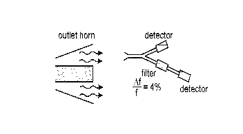
Operational principle: cut-off waveguides reflect microwaves with frequencies below certain value, and are transparent to microwaves with higher frequencies. An ensemble of circular waveguides packed together (so-called "microwave cut-off filter") operates similar to a stand-alone waveguide.

I. L. Bogdankevich, P. S. Strelkov, V. P. Tarakanov, et al. "A calorimetric spectrometer measuring single pulses of relativistic microwave generators". Instruments and Experimental Techniques, vol. 43, No. 1, 2000, pp. 82-87.

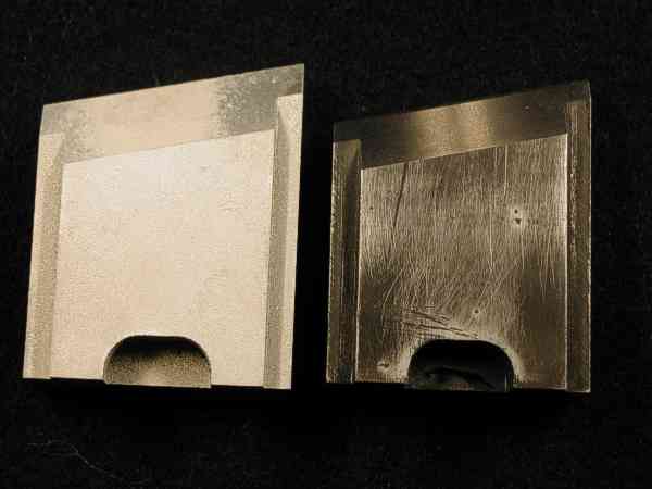
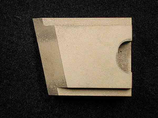
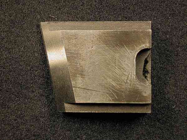
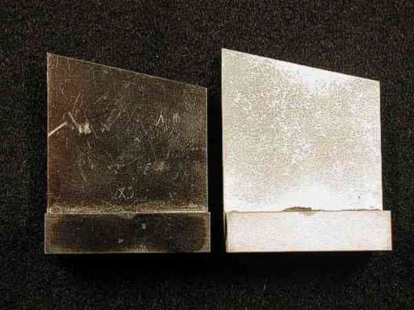
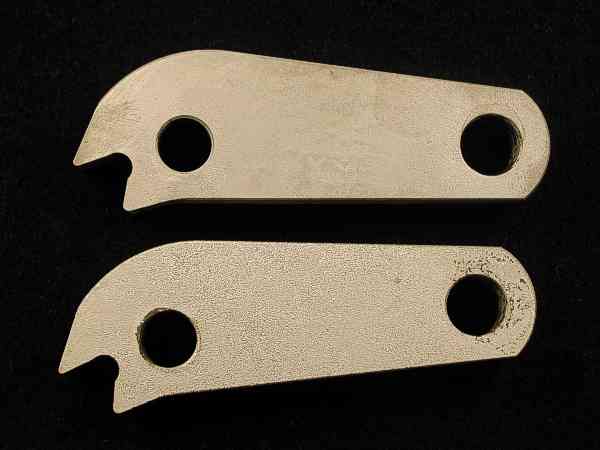
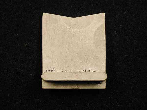
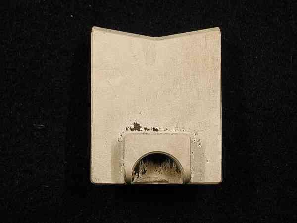
Main components: calorimeter(s), cut-off filter(s).

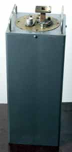
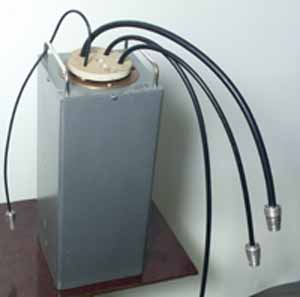
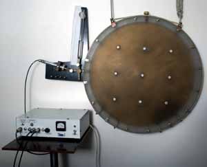
2-piece configuration: ring-shaped calorimeter to measure the fraction of lower frequencies reflected from the filter; disk-shaped calorimeter to measure the fraction of higher frequencies penetrated through the filter; two electronic blocks, one for each calorimeter; a set of cut-off filters; container.

Typical parameters: are determined mainly by that of calorimeter(s) (e.g., diameter 56 cm, sensitivity 0.15 J and frequency band 1.5 GHz - 60 GHz) and the set of filters.

Area of application: effective in case of bad reproducibility of microwave power from pulse to pulse.

Advantage: all the HPM power is registered irrespectively to its particular distribution. The ratio of the signals from the two calorimeters (which corresponds to the spectrum) varies less than the power.

1-piece configuration: ring-shaped calorimeter is absent, the gap between the horn and the filters is substantial (~ the longest wavelength emitted). The configuration is recommended in case of good reproducibility of HPM power from pulse to pulse. The configuration comprises one calorimeter, a set of several filters and the container.

Advantage: more simple in use and cheaper comparatively to the 2-piece configuration.

Drawback: it does not provide the information about the total HPM pulse power.